Perfromance Curve
Installation Position
The pump must always be installed with horizontal motor shaft within ± 5 °. The pump should be installed in the system in such a way that no major amount of air flowing through the pump or gathering in the pump housing will affect the pump when it is out of operation. If, in addition, a check valve is installed in the flow pipe, there is a high risk of dry running as the air cannot pass the valve.
- The pump is designed to be installed pumping upwards or downwards.
- Arrows on the pump housing indicate the liquid flow direction through the pump.
- if the pump is installed horizontally, the conduit box must point downwards. Be aware that the pump connection, flange or union nut, might interfere with the control box.
When making pipe connections, follow the piping manufacturer’s recommen
- Insert the check valve, if required.
- Refer to the arrows on the pump housing that indicate the direction of the liquid flow through the pump.
- Install the pump with horizontal motor shaft.
- Fit gaskets to the pump ends.
PWM Signal & Wiring
GRUNDFOS UPML and UPMXL PWM circulators are controlled via a digital low-voltage pulse-width modulation (PWM) signal which means that the speed of rotation depends on the input signal. The speed changes as a function of the input profile.These communication signals are standardized in the VDMA Einheitsblatt 24224 “Wet runner circulating pumps – Specification of PWM control signals”.
Digital low-voltage PWM signal
The square-wave PWM signal is designed for a 100 to 4000 Hz frequency range. The PWM signal is used to select the speed (speed command) and as feedback signal. The PWM frequency of the feedback signal is fixed at 75 Hz in the pump.
Duty cycle: d % = 100 x t/T
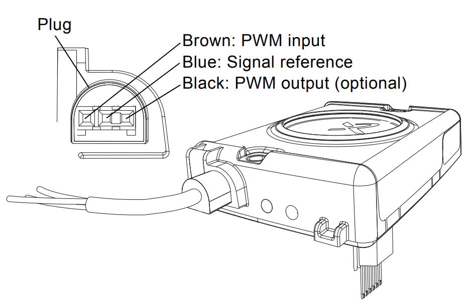
PWM Wiring
Dimensions


Reviews
There are no reviews yet.